
This page is initially going to look more like a BLOG with a progress report on various methods of packaging the ELS.
Initially the plan was to build a custom enclosure since there didn't seem to be anything large enough available that had a recessed top for the keypad overlay. Then I found the Hammond 946 series box.
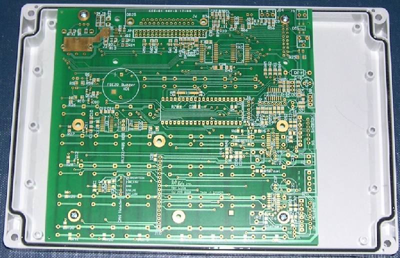
It's a close fit as the following pictures show.
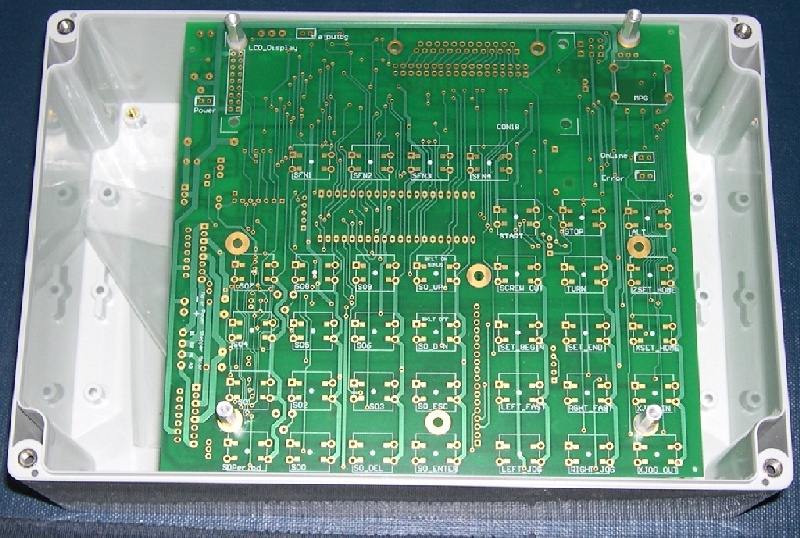
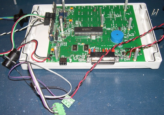
The board just fits inside the case. The back side of the case will need to be opened up for the connectors.
The problem is the lid.
The inside dimensions of the lid are smaller than the circuit board so it must sit on 0.625" (about 15mm) stand-offs to clear the inside edges. That puts the LCD display below the top surface of the lid. Until I cut the holes I won't know how it looks.
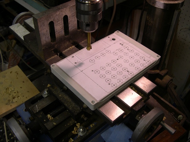
From a top view the drill guide shows where all the holes go.
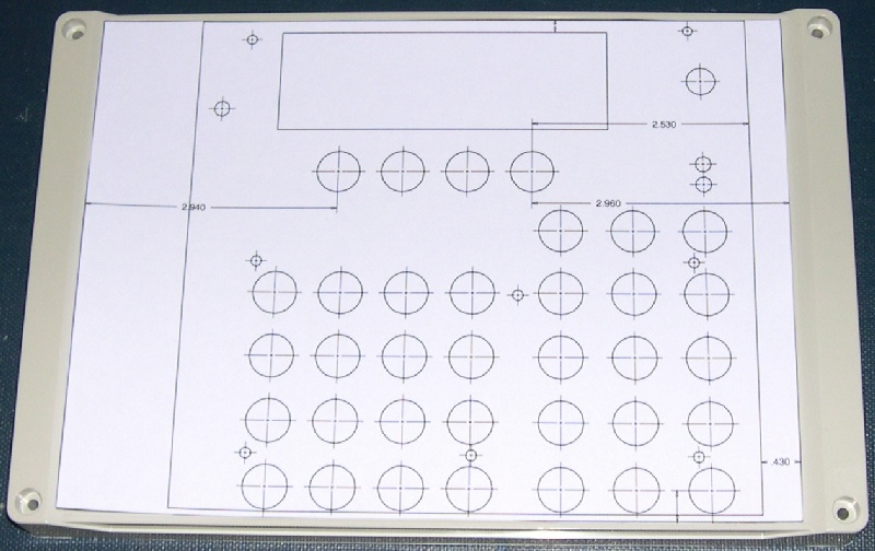
If the LCD were to project through the box and be even with the top surface the hole has to be as shown in the diagram. That means there is very little area for the keypad overlay to stick down above the display. The is a similar problem near the bottom edge with the button holes. Hopefully the overlay will have enough support from the sides to stay glued down. However, if the LCD does sit recessed below the lid, the LCD hole can be much smaller and there will be more room for the overlay to stick but it means some extensive milling on the inside of the lid to fit the PCB inside. If the PCB is mounted on standoffs below the surface of the lid then we'll need a spacer plate to hold button extensions.
The up side of using this box is the cost is low at only about $35 from Digikey. A custom box would be nearer $100.
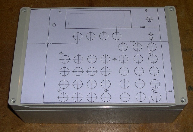
The next photo shows the box with the template glued in place. The trick here is to spray glue a thin layer on the paper and let it dry for 5 minutes. Then stick it down. Later it will come off but only if you didn't use too much glue. Lighter fluid removes the glue residue.
Next I drilled all the small holes and found only one was slightly out of place. I will update the template. I also used small 3/32 pilot holes to guide the tip of the Forstner bit.
Here are the small drilled holes.
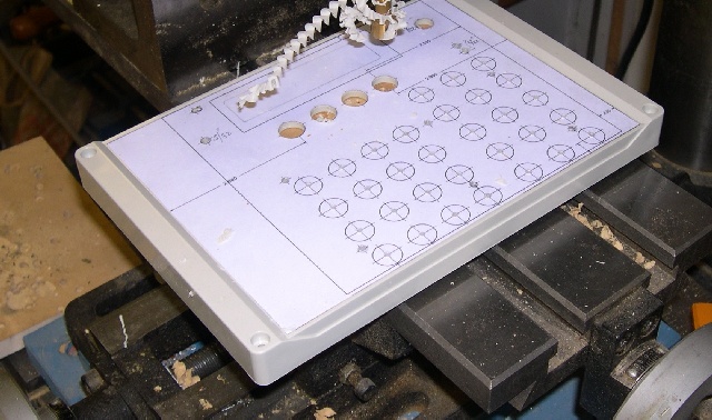
Then the larger holes. This is fairly tedious because the bit gets clogged with the bottom ring of plastic so after each hole I had to stop the drill press and restart it after cleaning the bit.
Initially I milled a cut-out around the display portion of the LCD. However, it sat so low that aesthetically and probably practically it really didn't work out. So I milled to the outside of the LCD. I am concerned that the overlay won't stay stuck down at the top. We'll have to see. The I flipped the cover over and milled away part of the edge of the box so the board would slip all the way down. Two plastic stand-offs were also cut away since they were in the way of the PC Board.
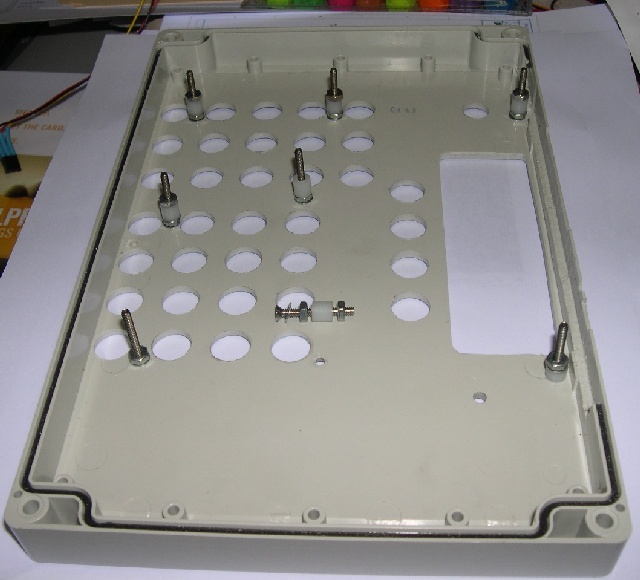
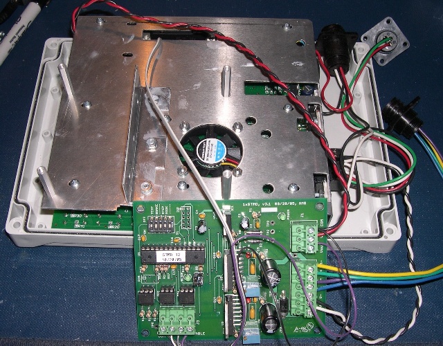
The above picture shows the results of the trial and error approach to getting the ELS board just right so the surface of the LCD display would be even with the top of the box. Notice the bottom right hand screw has a shorter spacer and only one nut. That's because the LCD display takes up some of the room. The other spacers are all exactly the same starting with a flat head 1" long screw, countersunk into the lid. Then a lockwasher, nut and quarter inch spacer followed by another 4-40 nut. The board sits level on all these posts and the 1" long 4-40 stand-offs in the spacer kit screw into these clamping and supporting the board solidly.
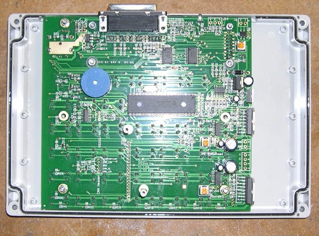
And here is the cover with the board installed, bottom view.
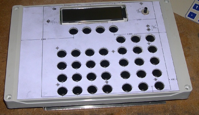
And then the top view. All it needs are thirty five 7/16"x 0.1" spacers on top of the buttons, the drilling template removed and then the keypad overlay glued in place.
The bottom half of the box still needs to have the back side notched and plate made to hold the stepper motor drive cable and power cable.
It occurred to me that I could mount the AVR_STMD inside the box connected to the X axis step/dir signals. I tapped 12V from the LCD backlight and Spindle supply jumpers and found a ground pin on the LCD backlight pins. I ran that up to the connector to power the AVR_STMD. The AVR opto-coupled step/dir signals connect in place of the jumpers on the header by the DB-25.
In the photo below I soldered the ELS 12V supply wires from the AMP connector directly to the board. The stepper supply and motor drive are through a removable connector.
Next I screwed down the back panel and inserted the small 0.1" spacing connector through the slot onto the X axis step/dir pins. The AVR board uses optical isolators and has an optically isolated enable pin so I wired those from the 5V connector to the power supply board. When the AVR is powered up the motors are therefore enabled too. Just about ready to go together.
This is a good place to point out that since I didn't assemble the parts in the right order some of the screws weren't accessible and so it came apart and went together a few times until I got it right.
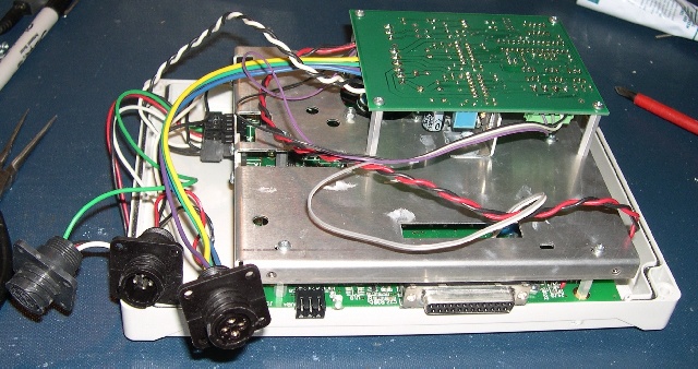
Finally! Ready for a back panel after some tie wraps to clean up the wires.
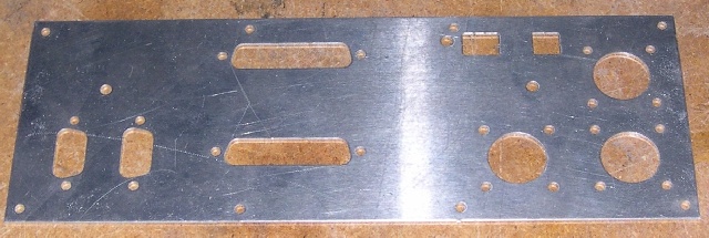
Here's a picture of the back panel.
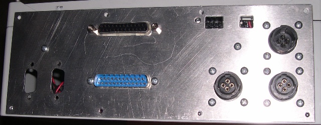
and now installed. I even permanently put in the DB-25 for programming so I wouldn't have to take apart the box for each upgrade. Still need to add a cable for the RS232 and CAN bus.
Stay tuned.